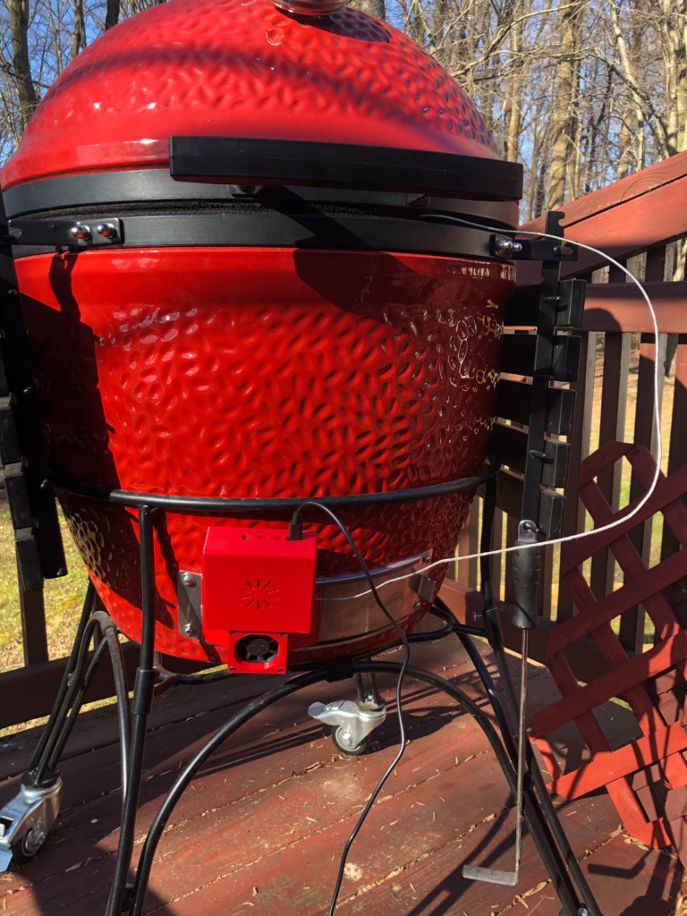
After spending hours of my time watching the temperature on the analog thermometer slowly rise, I designed a temperature control system for my kamado grill so I can get to the target temperature faster, grill food consistently, and grill without physically being present to manipulate dampers.
Design overview
The objective of the design is to create a controller for my kamado grill that forces air into the grill to increase rate of combustion of charcoal, thereby lowering cooking time, and be able to maintain a set temperature. Assembly of the controller consists of two main 3d printed components that hold together electronics and a fan.
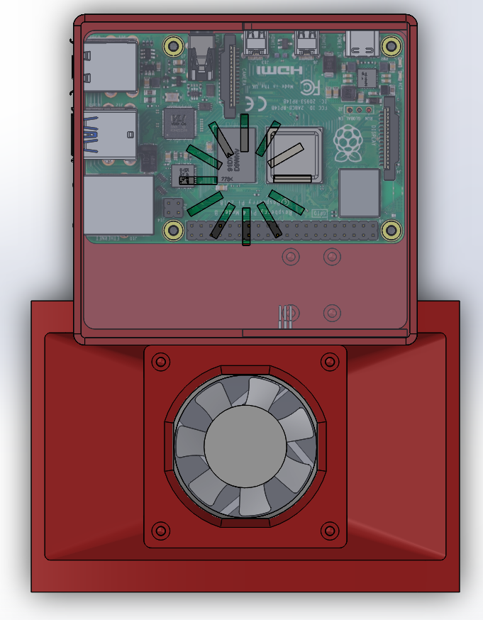
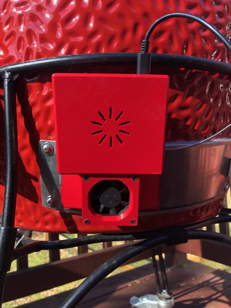
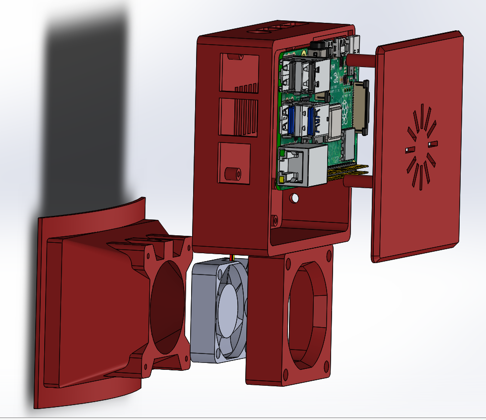
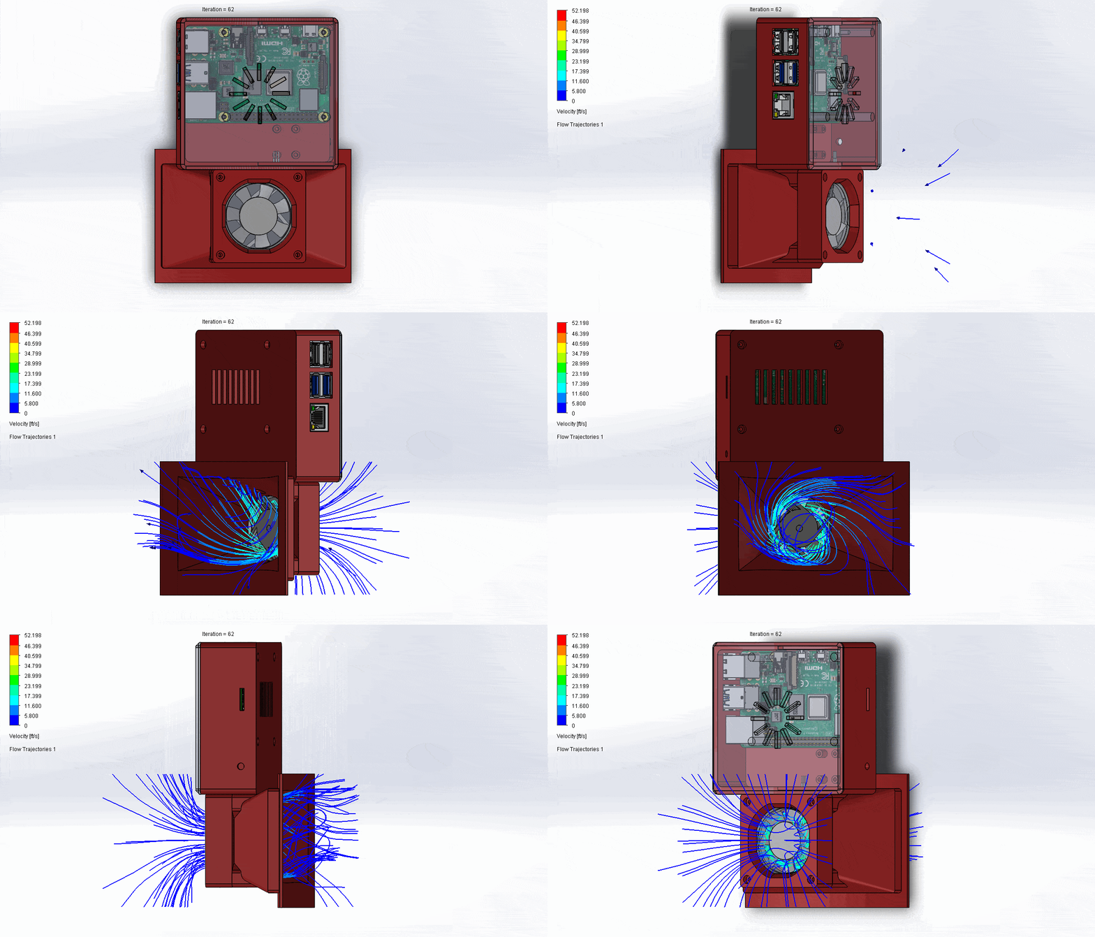
The first case component contains two housings, a lower housing that holds a fan that forces air into the grill at a rate of 10 cubic feet per minute at max RPM (ideally with no resistance), and above it is a housing that mounts a Raspberry Pi computer along with an analog-to-digital converter. The Raspberry Pi applies continuous power to the fan and provides a pulse-width modulation signal at a duty cycle determined by a PID algorithm to maintain the speed of the fan. Around the upper housing are openings for various computer peripherals and an opening for a thermocouple. A K-type thermocouple wire is placed inside the grill to measure the air temperature which provides feedback to the controller. The K-type thermocouple can measure temperatures up to approximately 2300°F which falls well over the maximum that I will be grilling anything and that the oven can support. Since the Raspberry Pi has no analog I/O pins, a MAX31855 analog-to-digital breakout board is mounted in the case adjacent to the Pi which takes in analog signals from the thermocouple and turns them into digital signals the computer can understand. Across the thermocouple leads of the MAX31855, I soldered a 1 uF capacitor to minimize electrical noise that was causing random spikes in the temperature data. After installing the electronics, access to the interior of the upper housing is sealed off with a cover that also holds the Raspberry Pi in place.
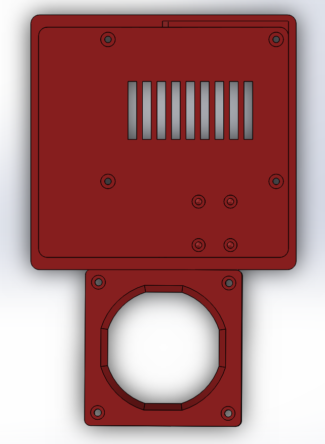
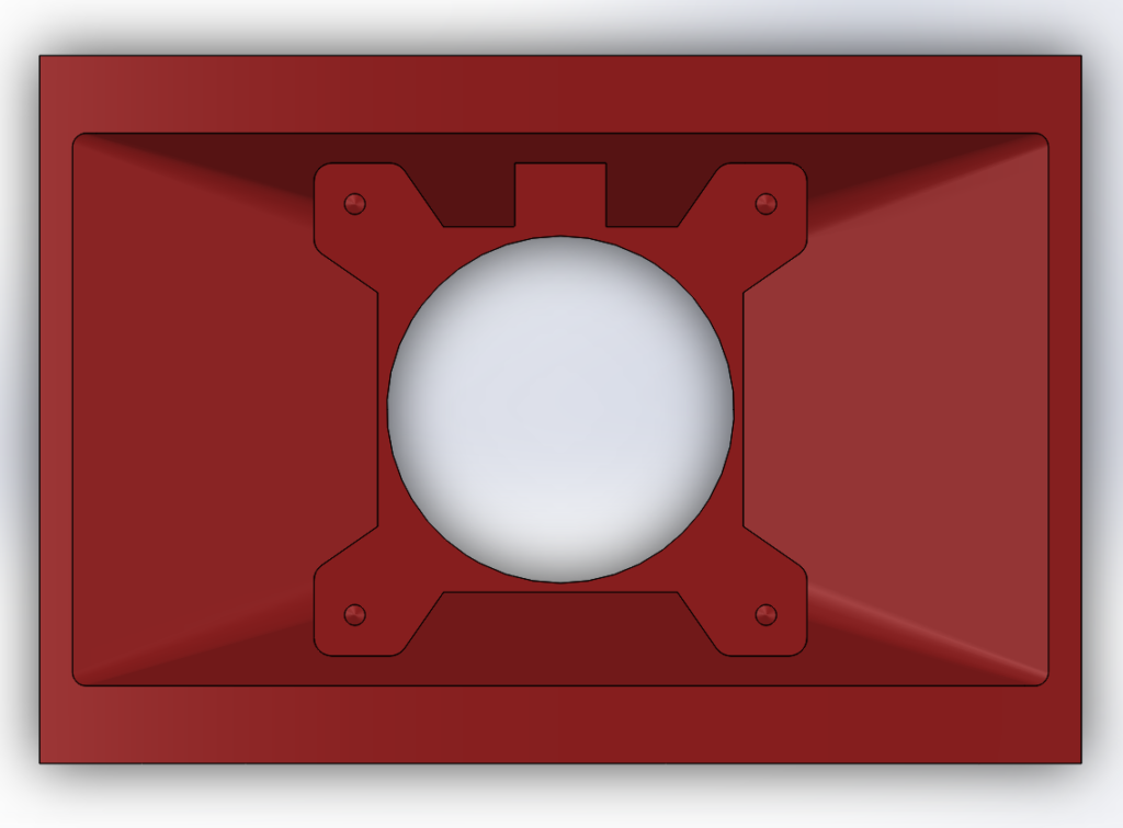
The second case component is the air intake which attaches onto the inlet of the kamado. It is sized to fit over the inlet when the damper is fully retracted and covers the entire inlet. In the assembly, the first case component mounts onto the air intake with 4-40 screws which hold the fan and both plastic case components together. As for the material construction of the case, the entire case assembly is 3d printed using PETG thermoplastic although originally, I printed in PLA, however the first few layers of the intake kept warping around the edges.
To control the fan, I ported my software from my brewing temperature control system which uses a web-based interface to communicate between the Raspberry Pi and any computer or smartphone that has access to my network. As a result, I can watch my grill temperature from my bedroom.
Combustion calculations and fan selection
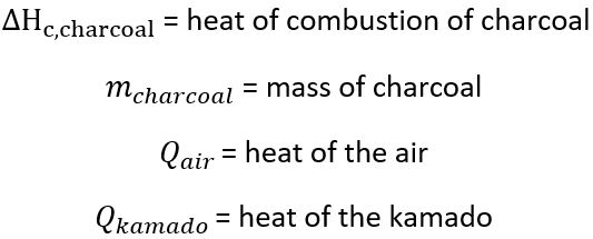
Fan selection was based on a few criteria. There needs to be enough air to combust charcoal in the shortest amount of time to raise the temperature high enough so I can sear a steak, but not high enough to damage the ceramic. To determine how much charcoal is needed to raise the temperature to 750 °F (max), I applied an energy balance across the kamado. During steady-state operation, there is only heat exchange between components in the system. The energy of the system is then:

where,
In an open system with no work, no change in height and assuming no change in cross-sectional area, the heat in the system is equal to the enthalpy of the system

where,
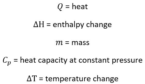
The energy balance can be written as

Rearranging and solving for the mass of charcoal in the kamado

I assumed a final air temperature of 1500 °F, as it doesn’t need to be accurate since air’s small mass has negligible impact on the grill’s final temperature. I found the heat of combustion of oak charcoal from FAO FORESTRY PAPER 63 which is 32500 kJkg-1.
Using the energy balance, the amount of charcoal needed to reach the max allowable temperature of the grill is

To calculate the amount of time it takes to combust all of the charcoal, I applied stoichiometry knowing that for every one part of carbon consumed, one part of oxygen is consumed.

According to FAO FORESTRY PAPER 63, the composition of oak charcoal is roughly 80% combustible carbon, where the rest is a balance of ash, volatiles, and moisture. With this information, I calculated the amount of time to burn all the coal. For the fan I am using CFM-4010-03-22, the max flow rate of air is 10 cfm.

Then the amount of time to burn all the charcoal is approximately
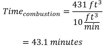
This is assuming complete combustion, operation at max RPM, and a well-mixed system where all the oxygen in the air is in complete contact with the charcoal at all times. 43 minutes is a really quick time. I would typically wait around that long playing with the dampers on the top and bottom of the grill just to reach around 250 F.
After installing and testing the fan, at low PWM, an audible high-pitch acoustic noise was present. The acoustic noise is the result of inductive kick from the fan motor from voltage spikes and impulse torque during each PWM cycle. To address both of these issues, I placed a 10 kΩ resistor and 1 uF capacitor on the PWM lead to lower the fan slew rate which solved the problem.
Testing the system
For the test, I did not attempt to do a controlled study. The whole purpose was to test controller functionality and understand the temperature dynamics of the process.
To start the test, I carelessly dumped about a pound of Royal Oak Natural Lump Charcoal onto the cast iron grate in the grill and then distributed it as evenly as I could. Afterwards, I used a butane torch and lit a small flame in the center of the charcoal mass. Next, I placed a heat deflector above the charcoal. Then I tried as best as I could and suspended the thermocouple wire in the center of the grill to avoid contact with any surfaces, and radiation from the flame. Finally, I closed the top damper to around half way. On my PC, I set the controller gains to Kp = 10, Ki = 0, Kd = 0, setpoint temperature to 150°F, and started the controller. I ran the test for about an hour. Below is a graph of my result.
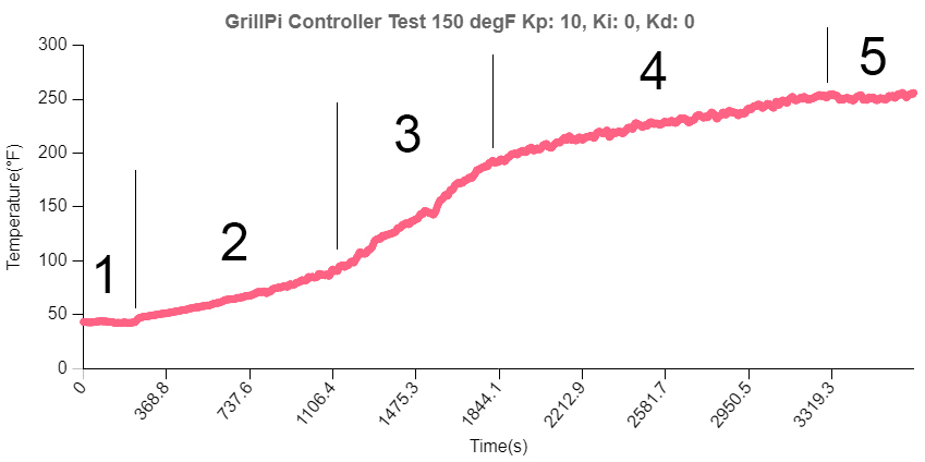
There are five notable regions in this graph where temperature changes have occurred.
Region 1
At first, the controller is off. I initiated the step change early on so there is some dead time although I’m not exactly sure how much. I did not program a plot of the RPM or duty cycle (yet) so it’s hard to tell when. At around 3 minutes (180 seconds), a rise in temperature can be seen.
Region 2
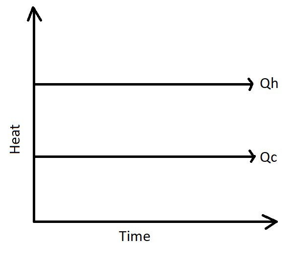
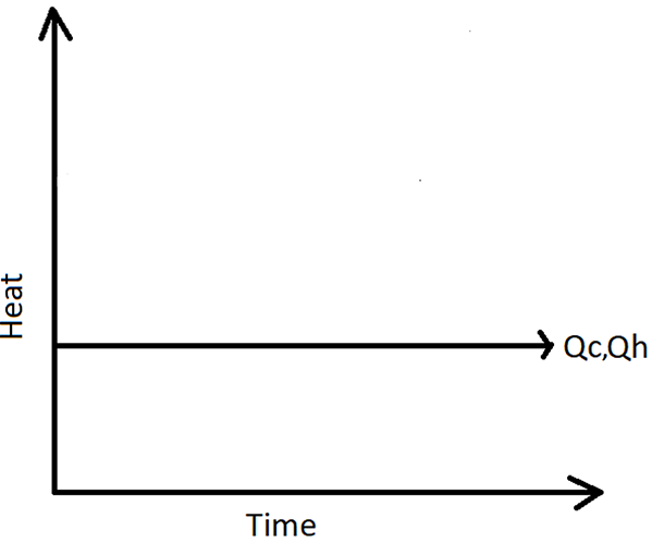
The temperature rise is linear and stable. Within this region, the controller is operating at 100% duty cycle and fan at max RPM. Near the end of the region at around 1100 seconds (~18 min), m(t) = Kp (Tset-Tactual) = 10 * (150-95) = 550% adjusted to 100%. The profile here is similar to my brewing controller temperature profile which represents an integrating process. In this region, the heat generated (Qh) by the charcoal is around constant but greater than the amount of heat being removed (Qc) from the grill, which leads to a linear rise in temperature.
Region 3
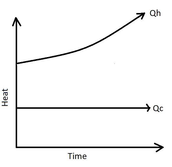
The temperature becomes unstable. Fire inside the grill is spreading fast although the fan has shut off. The actual temperature overshot the setpoint at 150°F and continued to rise rapidly.
Region 4
Flames in the grill have died down, the rise is now similar to region 2 until around the end of the hour where the grill began to approach steady-state.
Region 5
At approximately 30 minutes after the fan shut off, temperature has reached a new steady-state. The total overshoot is around 100 °F from the set point.
Analysis
So what insights can be gathered from my test run? For one, the proportional gain Kp = 10, is too large as the process is self-integrating. Fire will continue to spread without forced air, as long as air is present. If too much air is supplied for a long time, it can lead to thermal runaway where the temperature of the air will rapidly increase and will be difficult to reduce by reducing the flow rate from the fan alone as the fire has grown in considerable size. This means proportional control action needs to be less aggressive if a low set point is desired. The maximum temperature at which the controller is operating at 100% duty cycle is

which occurs approximately at 1500 seconds, and 200 seconds later, the grill is able to climb those additional 10 degrees. In this region, the temperature is in runaway, so the time for fan speed reduction is way past the point at 1100 seconds (~18 min) when runaway occurs. The gain needs to be reduced significantly to counter the likelihood of runaway which is very challenging to determine. There are many controllable and uncontrollable factors that influence the dynamics of the temperature profile which include measurement related factors (sensitivity, location), and process related factors (% open of the top damper, mass of coal, distribution of coal, coal type/brand, size of the initial flame, flame location, fire starter use, heat deflector use, humidity) so it’s difficult to get consistency (or even optimal behavior) between runs.
In addition to reducing proportional gain, the integral gain is good to keep at 0 as more integral contribution from the controller will result in greater overshoot. However, derivative action may prove to be useful as the system has high thermal inertia and may scale back the fan speed leading to less overshoot.
Next steps
My plan is to get more thermocouples and measure the surface temperature of the ceramic at a level where the grill rack is and a third location between the space of the heat deflector and interior wall of the kamado to better understand the temperature distribution where the food will approximately be sitting. It will give me an idea of the lag between locations so I can settle on what profile would be better to use for controlling fan speed.
After learning more about my grill’s temperature distribution, I will attempt to run a more experimentally rigorous study. I’m thinking of creating a run sheet with few factors and seeing what the response is under different conditions. I will also attempt a heuristic tuning method, possibly Ziegler-Nichols for integrating processes and evaluate how reliable it is at proving a quick, stable, and accurate response.
As for future case development, I also want to revisit an earlier idea I had where I wanted to make the controller wireless by having a power bank capable of powering on the Pi and fan for at least 10 hours. However, after buying the power bank, its size made me reconsider (and redesign) the air intake where I settled on a solution without one. I think I’ll try to incorporate the power bank by removing the batteries and contacts and extend the depth of the upper housing of the first plastic component to position my rechargeable power supply.
This concludes my experiment. Thanks for reading, and hopefully you’ll stick around for my next post diving deeper into grill temperature control.
Leave a Reply